The analog computer
The electric slide rule was distributed in kit for self-construction, pompously called analog computer.
The analog computer had a brief golden age in the early 60s, but you can easily build one: it's cheap and funny.

In the '60 large scales were needed due the imprecision of the pots
How it works
The schematic I propose is inspired by the article "Archimede, calcolatore elettronico" (Sperimentare, July 1968), without the addition and subtraction circuit, which requires a complicated voltage stabilization. At the time it was necessary to grade the scales by hand according to the characteristics of each potentiometer, but now they can be purchased with ready-made and precise pot-knobs.

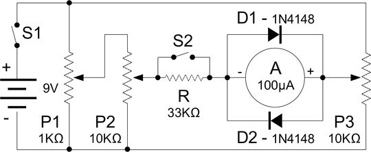
The circuit diagram: just three potentiometers and an ammeter
Let's have a look at the diagram. The battery and the central zero ammeter are connected in one side through the potentiometers P1 and P2, on the other through P3, all graduated with scales from 1 to 10. When all are settled to the same value the instrument will read zero.
To perform 8x5 we set P1 on 8 (20% of the resistance) and at the output we will have 80% of the input current which will feed P2 positioned on 5 (50% of the resistance). At its output the original current will be 50% of 80% (40%) and will move the instrument's needle from the central zero.
Now we rotate P3 until the instrument reads zero. This will happen when the potentiometer is at 40% of the scale, 4, and its output perfectly balances the 40% of P1 and P: 40 is just the result of 5x8! All the operations are settled like in a classic slide rule, decimals and commas being calculated by mind as usual.
To perform a multiplication we need just to set multiplicand and multiplier on P1 and P2, turning after P3 until the instrument reads zero and then read the result on its scale.
Because we treat percentages the results will always be correct, whatever the input voltage. All the operations can be done, but it's difficult to made addition and subtraction because in this case the voltage must always be accurate and stable: 1.5 volt + 1.5 volt will read 3 volts on the voltmeter.
The error in the calculations (ca. 2.5%) is higher than on standard slide rules, despite today we have economic and precise potentiometers which instead in the 60s were expensive and with a poor linearity. (the relationship between angle of rotation and resistance). Due to the unreliability of these components the analog calculators met very little success.

Analogic computer Science Fair kit
What you need to build one
- 1 9-volt battery, its voltage however does not affect the results.
- 3 precision potentiometers (P) linear multiturn (10 turns, tolerance: 5% linearity: 0.25%, power-rating about 2W) with their precision knobs. The resistance value does not affect the results, but P2 must be 10 times greater than P1 in order to limit the losses of linearity due to the loading. Use P1 of 1k?, P2 and P3 of 10K?.
- 1 analog ammeter of 100 uA with central zero (A). As protection we have 2 diodes (D1 and D2) model 1N414. 1 resistance (R) from 33KO with 1 pushbutton switch (S2 or ZERO) is needed to exclude the protection for precise readings.
- 1 power switch (S1).
- 1 mounting base, I used an acrylic photo frame, easy to pierce with the hole saws. Instead of a photo I inserted in the frame the layout of the front.


Different models of precision pot knobs
How to use it
Multiplication:
- set multiplicand and multiplier on P1 and P2;
- turn P3 until the instrument reads zero, then read the result on its knob.
Division:
- set dividend and divisor on P3 on P2;
- turn P1 until the instrument reads zero, then read the result on its knob.
Elevation to the square:
- set the same number on P1and P2;
- turn P3 until the instrument marks zero, then read the result on its knob.
Square root:
- set the number on P3;
- turn P1 and P2 turn P3 until they indicate the same number and the instrument reads zero;
- the result is the number indicated from both P1 and P2.
To properly center the needle on zero press S2 (ZERO) to sharpen the reading.
Turn the knobs with care to not overloading the instrument. When possible avoid to use the lower end of the scale (eg. to perform 5x5 set 500x500, not 005x005. Remember that, as in the slide rules, commas and decimals are relative and must be positioned by mind.
If the ammeter reads zero but the result read on the knob is wrong, you must account for this error or adjust the P3's knob.

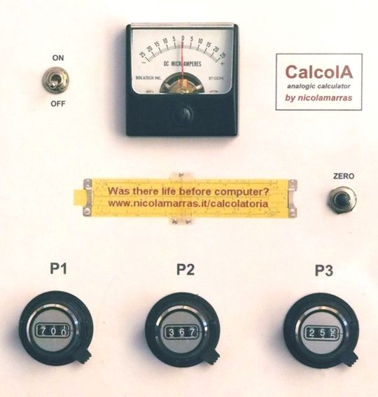
The calculator mounted in photo frame

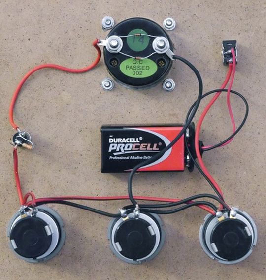
Back of the calculator with the simple wiring

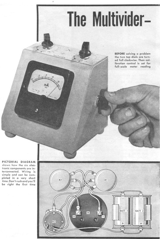
The Multivider electric slide rule
My presentation of the electric slide rule to the Oughtred Society
Links: Electric Slide Rules - Analog computer on Wikipedia
© 2004 - 2026 Nicola Marras Manfredi

